Climate change mitigation is about reducing greenhouse gas (GHG) emissions. The worldwide goal is to reach net zero, which means balancing the amount of GHG emissions produced and the amount removed from the atmosphere.
On the one hand, this implies reducing emissions by using low-carbon technologies and energy efficiency. On the other hand, it implies deploying negative emission technologies such as carbon storage, which is the subject of this post.
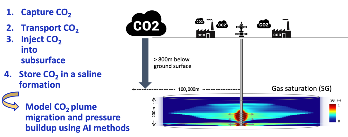
Carbon capture and storage (CCS) refers to a group of technologies that contribute to directly reducing emissions at their source in key power sectors such as coal and gas power plants and industrial plants. For emissions that cannot be reduced directly either because they are technically difficult or prohibitively expensive to eliminate, CCS underpins an important net-negative technological approach for removing carbon from the atmosphere.
If not being used on site, CO2 can be compressed and transported by pipeline, ship, rail, or truck. It can be used in a range of applications or injected into deep geological formations (including depleted oil and gas reservoirs or saline formations) that trap the CO2 for permanent storage. This unique dual ability of CCS makes it an essential solution among the energy transition technologies that mitigate climate change.
In addition to the role CCS plays in the energy transition, it is a solution for challenging emissions in heavy industries and addresses deep emissions reductions from hard-to-abate sectors like steel, fertilizer, and cement production. It can also support a cost-effective pathway for low-carbon blue hydrogen production.
In numbers, CCS facilities currently in operation can capture and permanently store around 40 Mt of CO2 every year. According to the International Energy Agency (IEA), to achieve a climate outcome consistent with the Paris Agreement, 1150 MtCO2 must be stored before 2030. So, there is a factor of 30 to achieve in storage capacity by 2030 to reduce the emissions of power and industrial sectors.
Global macro-trends such as the rise of environment social governance (ESG) criteria are stimulating the implementation of the broadest portfolio of technologies, including CCS to achieve net-zero emissions at the lowest possible risk and cost. Investment incentives are therefore building unprecedented momentum behind CCS with plans for more than 100 new facilities already announced in 2021.
CO2 injection problem
Carbon must be stored somewhere. It is most often stored underground in a process called geological sequestration. A geological formation is only selected as a storage site under certain conditions to make sure there’s no significant risk of leakage and no significant environmental or health risk.
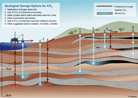
This involves injecting carbon dioxide into underground rock formations. It is stored as a supercritical fluid, meaning that it has properties between those of a gas and a liquid.
When CO2 is injected at depth into a reservoir, it remains in this supercritical condition as long as it stays in excess of 31.1° C and at a pressure in excess of 73.86 bar. This is true whether the reservoir is a saline formation or depleted oil and gas fields.
CO2 must be sealed under a capillary barrier so that carbon remains stored for hundreds of years or even indefinitely in a safe way. Otherwise, if CO2 leaks out in large quantities, it could potentially contaminate a nearby aquifer. If it leaks to ground surface, it can cause safety hazards to nearby humans or animals.
The overall performance of such storage can be predicted numerically by solving a multiphase flow problem. However, this requires solving highly nonlinear PDEs due to multiscale heterogeneities and complex thermodynamics.
The numerical simulation methodology to achieve this usually consists in several steps:
- Collecting data and information about the subsurface geology and properties.
- Building a geological model of the storage formation and its surroundings.
- Building a dynamic model of the reservoir, which is used to simulate CO2 injection and CO2 evolution inside the reservoir. These dynamic simulations are used to evaluate and optimize key performance indicators related to reservoir conditions.
Traditional simulators can accurately simulate this complex problem but are expensive at sufficiently refined grid resolution. Machine learning models trained with numerical simulation data can provide a faster alternative to traditional simulators.
In this post, we highlight the results using the newly developed U-FNO machine learning model and show its superiority for CO2-water multiphase flow problems required for understanding and scaling CCS applications.
Simulation setup
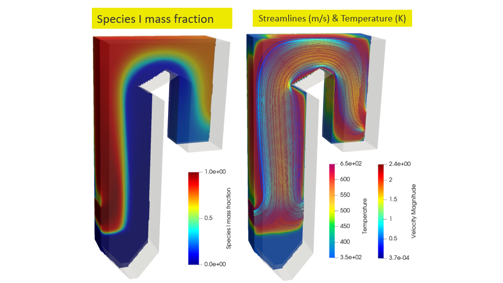
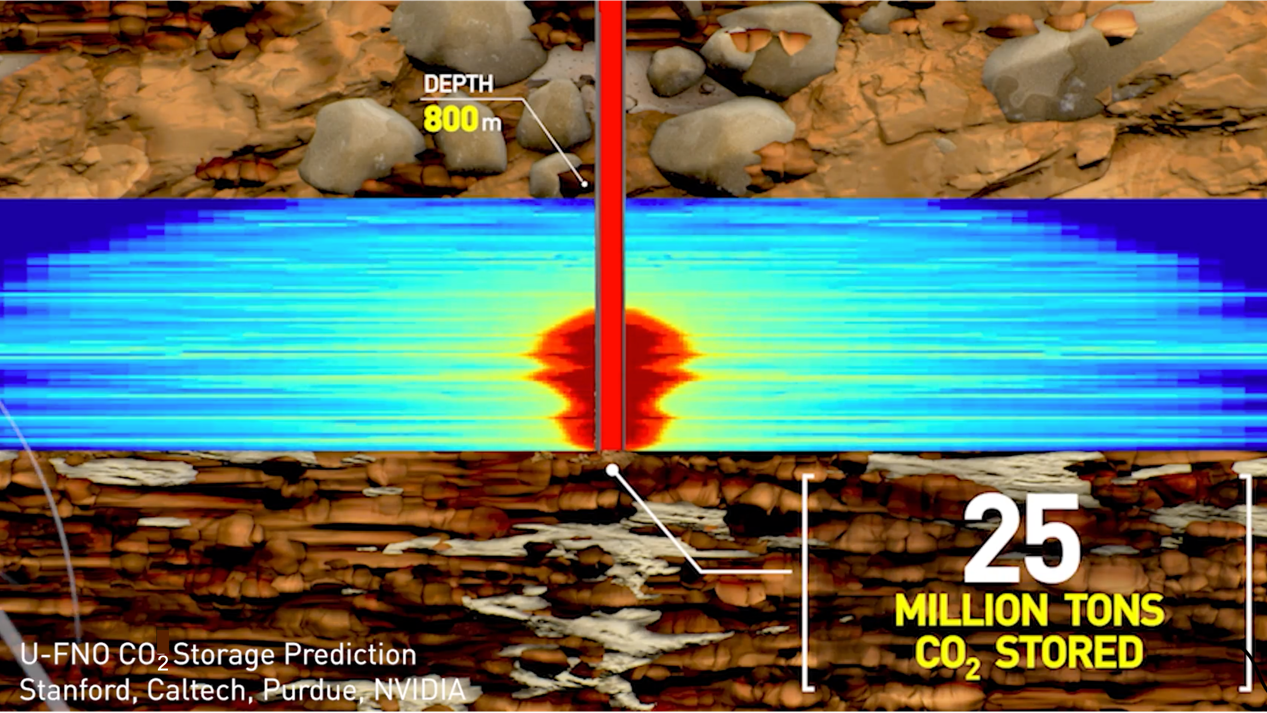
We consider modeling gas saturation and pressure over 30 years in deep saline formation at a constant rate ranging from 0.2 to 2 Mt/year. The x-axis and y-axis are the reservoir thickness and reservoir radius in meters, respectively.
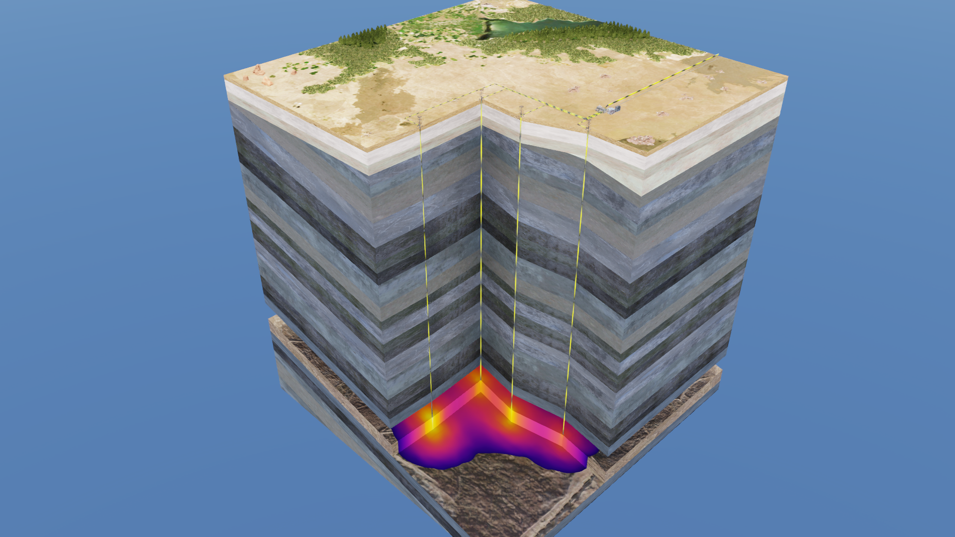
The setup is a realistic reservoir located at least 800 m below ground surface (Figure 2). The setup enables reservoir simulation at various realistic depths, temperature, formation thickness, injection pattern, rock properties, and formation geology.
The numerical simulator Schlumberger ECLIPSE (e300) is used to develop the multiphase flow dataset for CO2 geological storage. Super-critical CO2 can be injected through a vertical injection, well with various perforation interval designs into a radially symmetrical system x (r, z).
A novel Fourier neural operator
In a recent paper published in Advances in Water Resources, four types of machine learning model architectures are studied:
- The Fourier neural operator (FNO) proposed in Fourier Neural Operator for Parametric Partial Differential Equations
- A newly proposed U-FNO
- A conv-FNO that uses conv3d instead of U-Net
- The state-of-the-art benchmark CNN used in U-FNO–An enhanced Fourier neural operator-based deep-learning model for multiphase flow
The goal of a neural operator is to learn an infinite-dimensional-space mapping from a finite collection of input-output observations. In contrast to the original Fourier layer in FNO, the U-FNO architecture proposed here appends a U-Net path in each U-Fourier layer. The U-Net processes local convolution to enrich the representation power of the U-FNO in higher frequencies information.
The newly proposed U-FNO model architecture uses both Fourier and U-Fourier layers (Figure 3).
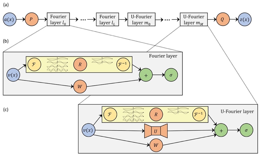
In the Fourier and U-Fourier layers (a):
is the input.
and
are fully connected neural networks.
is the output.
Inside the Fourier layer (b):
denotes the Fourier transform.
is the parameterization in Fourier space.
- $latex F−1$ is the inverse Fourier transform.
is a linear bias term.
is the activation function.
Inside the U-FNO layer (c):
denotes a two-step U-Net.
- The other notations have identical meaning as in the Fourier layer.
- The number of Fourier and U-Fourier layers,
and
, are hyperparameters, optimized for the specific problem.
Comparisons with the original FNO architecture and a state-of-the-art CNN benchmark shows that the newly proposed U-FNO architecture provides the best performance for both gas saturation and pressure buildup predictions.
The results of CO2 storage predictions using NVIDIA GPUs show the following:
- U-FNO predictions are accurate, with only 1.6% plume error on gas saturation and 0.68% relative error on pressure buildup.
- U-FNO has superior performance on both training and testing sets compared to CNNs and the original FNO.
- Gas saturation and pressure buildup prediction using U-FNO is 46% and 24% more accurate than state-of-the-art CNNs.
- U-FNO requires only 33% of the training data to achieve the equivalent accuracy as CNNs.
- Running a 30-year case on GPUs using U-FNO takes 0.01 s compared to 600 s using traditional finite-difference methods (FDM).
- U-FNO is 6 x 10⁴x faster than the “ground truth” conventional FDM solver; FNO is 105 x faster.
The training and testing times are both evaluated on an NVIDIA A100-SXM GPU and compared to Schlumberger ECLIPSE simulations on an Intel Xeon Processor E5-2670 CPU.
For the CO2-water multiphase flow application described here, the goal was to optimize for the accuracy of gas saturation and pressure fields, for which the U-FNO provides the highest performance. The trained U-FNO model can therefore serve as an alternative to traditional numerical simulators in probabilistic assessment, inversion, and CCS site selection.
Web application
The trained U-FNO models are hosted on an openly accessible web application, CCSNet: a deep learning modeling suite for CO2 storage. The web application provides real-time predictions and lowers the technical barriers for governments, companies, and researchers to obtain reliable simulation results for CO2 storage projects.
Scaling FNO to 3D problem sizes using NVIDIA Tensor Core GPUs
Due to the high dimensionality of input data in CO2 storage problems, machine learning application has been limited to two-dimensional or small to medium-scale three-dimensional sized problems.
To overcome this limitation, a recent study proposed a model-parallel version of FNOs based on domain-decomposition of both the input data and network weights. For more information, see Towards Large-Scale Learned Solvers for Parametric PDEs with Model-Parallel Fourier Neural Operators.
Performing domain decomposition methods with minimum communication amount for parallelization of multidimensional fast Fourier transforms (FFT)s has been extensively looked at in literature, for many applications.
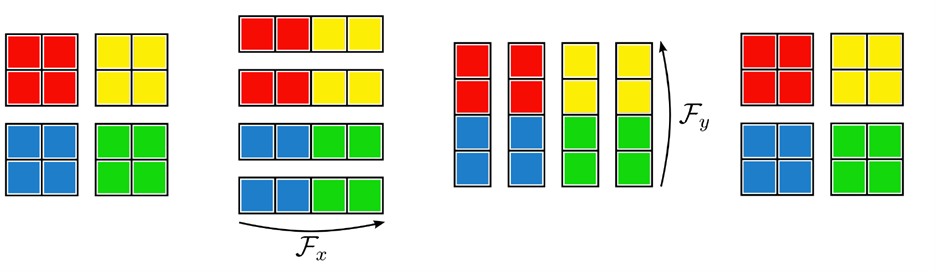
It is well-known that you can efficiently compute a multidimensional FFT with a sequence of lower-dimensional FFTs. The main idea is to use an iterative repartition pattern. The full mathematical derivation of the required components of distributed FNOs and its implementation is provided in the previously mentioned paper.
The following figure shows this concept, showing the distributed FFT using pencil decompositions acting on an input initially distributed over a 2×2 partition. Repartition operators are used to ensure that each worker has the full data it needs for calculating the sequential FFT in each dimension.
The authors demonstrated that this implementation offers a different set of features when solving the 3D time-varying two-phase flow equations. In this case, the model-parallel FNO can predict time-varying PDE solutions of over 3.2 billion variables using up to 768 GPUs (128 nodes) on Summit.
Looking ahead towards next steps, we can train larger 3D models following the Grady approach based on domain-decomposition, and drastically increase our capability on data size. With this technique, it is possible for us to scale up FNO type models to solve 3D basin/reservoir CO2 storage problems.
Summary
Simulations are required to optimize the CO2 injection location and verify that CO2 does not leak from the storage site. We have shown that U-FNO, an enhanced deep Fourier neural operator, is 2x more accurate, 3x more data efficient than state-of-the-art CNN, and four orders of magnitude faster than a numerical simulator.
Using NVIDIA GPUs, the trained U-FNO models generate gas saturation and pressure buildup predictions 6 × 10⁴x faster than a traditional numerical solver. Distributed operator learning and the ability to scale FNOs with domain decomposition to large problem sizes opens up new possibilities to scale our studies to realistically sized data.
To avoid the worst outcomes from climate change, Working Group III published the 2022 mitigation pathways in its contribution to the sixth assessment report (AR6) of the Intergovernmental Panel on Climate Change (IPCC). Experts highlighted the need for and potential of carbon capture and storage (CCS) to limit global warming to 1.5° C or 2° C.
Admittedly, there are current limitations to this set of technologies, especially related to economic and sociocultural barriers. But its deployment to counterbalance hard-to-abate residual emissions is considered unavoidable if net zero CO2 or greenhouse gas emissions are to be achieved.
We believe that building powerful AI tools for climate action and resilience can curb emissions at scale. In this work, we deployed novel artificial intelligence techniques to accelerate the CO2 flow in porous media, which play an important role for CCS applications and the path forward towards mitigating climate change.