3D transforms on iOS under the hood part II: Perspective shifts
The Setup
In the previous write-up (How do 3D transforms of iOS views work under the hood?), I mentioned briefly that changes in POV were handled by a specific entry in the transformation matrix, m34. I noted how the derivation was a whole separate thing in and of itself, so here’s the overview of how we are able to understand why this entry affects perspective!
We start with a handy dandy diagram again, looking at a graphical depiction of the user, the screen, and an arbitrary point of a UIView of your application in 3D space. Let's run through the variables we've defined in this first graph (Figure 1).
Here, we have a point P which represents any given point of a UIView in our application. We'll say its coordinates are (x, y, z). Recall from our last article, that (x, y) is the actual CGPoint coordinate pair, while z refers to the view's layer.zPosition property.

Figure 1: A user viewing an arbitrary point of a view through the device screen, in 3D space.
We also have a point C to represent the user’s eyes - if you did look at that Wikipedia link I tagged in the previous article, you’d have found that C referred to a ‘camera’, but it’s the same principle here. We’ll say the user is located at some arbitrary location in our xyz-space, at (xc, yc, zc).
How does the user C view this point P? They observe it through the viewport on the screen, which is a 2D plane. P is linearly projected onto that plane, meaning it is mathematically mapped to a corresponding coordinate on that 2D surface. The user then sees not the original point P, but rather that projected point.
Let’s call this projected point P', and give it some coordinates as well, (xp, yp, zp), representing coordinates on that plane.
While the concept applies in this setup perfectly fine, since the screen is a 2D plane, for convenience’s sake we can place it alongside the xy-plane. This simplifies our coordinates and therefore our calculations a fair bit.
We’ll therefore start our work based off this second diagram (Figure 2). You can see that the point P' is now simplified to have a z-coordinate of zero, i.e. (xp, yp, 0). Also, we’ve shifted our user such that they lie directly along the z-axis, i.e. their coordinates are now (0, 0, zc).
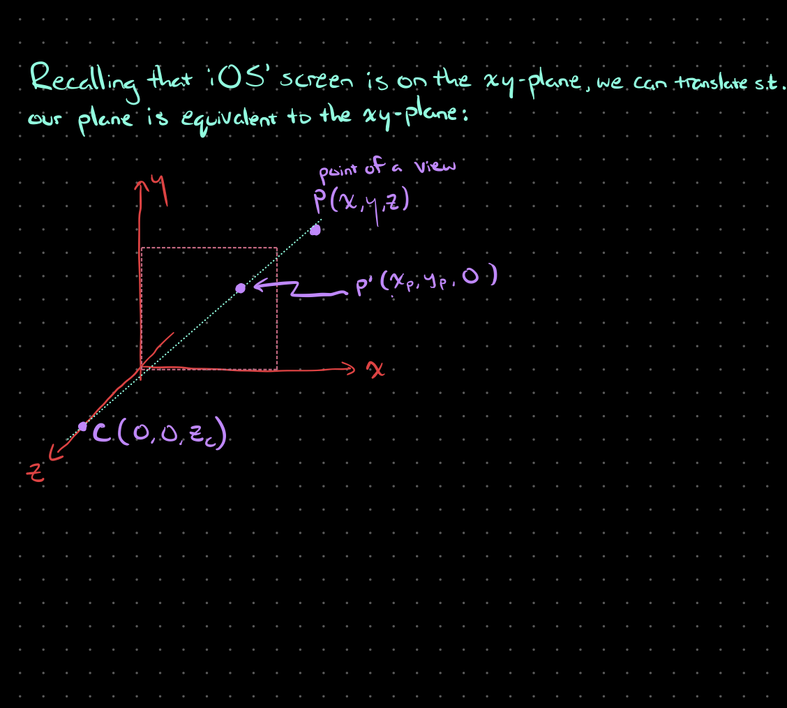
Figure 2: The same setup of a user in 3D space, just translated such that the plane representing the device screen, aligns with the xy-plane, and placing the user along the z-axis.
Describing the projected point using the user coordinates + the original coordinates
N.B.: the handwritten derivation is attached at the end (Figure 3)
Right, so how can we describe this projected point (whose coordinates are unknown), in terms of the point of the original view (which is known), and the location of the user? Well, using the fact that we’re performing a linear projection here, let’s draw a line segment from the user C straight through to the original point P. Now, we have a couple of line segments, CP' and P’P, in addition to the original CP. Let’s focus on CP' here.
CP' and CP are clearly parallel. How does that help us? Well, it lets us leverage a handy set of properties called direction cosines! Briefly, direction cosines are the cosines of the angles that a line makes with the positive half of each of the coordinate axes (i.e. in 3D space, we have a direction cosine for the x-axis, one for the y-axis, and one for the z-axis). Thanks to trig, we know that cosine is A/H (adjacent over hypotenuse).
Using that simple fraction, we can say the direction cosines are the following, using each axis of CP':
       0  -  x          0  -  y          z   -  0
              p                p          c
k    = --------, k    = --------, k    = --------
 1x       CP'     1y       CP'     1z       CP'
where k1x is the direction cosine for CP' in the x-axis, k1y the direction cosine for CP' in the y-axis, and k1z for the z-axis.
Since each direction cosine value is a constant, let’s absorb the denominator by multiplying both sides of each equation to leave us with k1x = - xp, k1y = -yp, and k1z = zc.
By the same logic for the line CP, we can arrive at the following:
                                       z   -  z
       0  -  x         0  -  y          c
k    = -------, k    = -------, k    = --------
 2x      CP      2y      CP      2z       CP
where k2x is the direction cosine for CP in the x-axis, k2y the direction cosine for CP in the y-axis, and k2z for the z-axis. And again, simplifying by absorbing the denominator into the constant on the other side of each equation, we arrive at: k2x = -x, k2y = -y, and k2z = zc - z.
Remember when we said CP' and CP were parallel? Well, that tells us the two sets of direction cosines are also equivalent (since for them to be parallel, they naturally have to be positioned such that they make the same angles against each axis). This is great, because we can say that for each axis, k2 / k1 = 1. Hence, we can create the following:
k                           z   -  z
 2          - x      - y     c
-- =  1  = ----- =  ----- = --------
k           - x      - y       z
 1             p        p       c

       x     y           z
 ==>  --- = --- =  1  - ---
      x      y           z
        p      p          c
We wanted the describe the coordinates of P' in terms of everything else. We can now do that by rearranging these equivalences to isolate xp and yp. Looking at the x-ratio to z-ratio relation first, we see:
 x           z
--- =  1  - ---
x           z
  p           c

              x
 ==> x   = --------
      p           z
           1  -  ---
                 z
                  c
And in the same manner, examining the y-ratio to z-ratio next, we get:
          y
y   = --------
 p           z
      1  -  ---
            z
             c
Almost there! Time to tie this all back to matrices.
Matrix representation of our derived relations
To get our matrix representation, let’s recall that our simplest CATransform3D matrix is the identity matrix.
And recall that applying it to a set of coordinates directly, results in no change (i.e. no transformation actually occurs).
To see how we can apply a pure perspective shift (no other scaling, translating, or rotating), let’s take that identity matrix as our base, and see how we can create a matrix that gets us from (x, y, z) to (xp, yp, zp).
Adding that extra dimension, and doing some acrobatics, you’d arrive at the following:
                                     _                 _
                                    | 1   0   0    0    |
                                    |                   |
                                    | 0   1   0    0    |
                                    |                   |
[x    y    z    1] = [x   y   z   1]|              - 1  |
  p    p    p                       |             ----  |
                                    | 0   0   1    z    |
                                    |               c   |
                                    |                   |
                                    |_0   0   0    1   _|
If you perform the matrix multiplication on the right hand side, you would find that this equation becomes:
    _                     _
   |                    1  |
 = | x   y   z   1  -  --- |
   |                   z   |
   |_                   c _|
And, remember what the last step the rendering engine does is before arriving at its final new set of coordinates? That’s right, normalization. So you normalize by the last entry in the matrix, and you’ll see that you have:
    _                                  _
   |     x          y          z        |
   | --------   --------   --------   1 |
 = |        1          1          1     |
   | 1  -  ---  1  -  ---  1  -  ---    |
   |       z          z          z      |
   |_       c          c          c    _|
Dropping the 1 at the end then gives the engine the transformed coordinates. As you can see, this final coordinate set matches our expectation from right before, where we stated that for xp and yp:
          x               y
x   = --------, y   = --------
 p           1   p           1
      1  -  ---       1  -  ---
            z               z
             c               c
Thus, our matrix representation checks out, and our transformation matrix for a pure perspective change is in fact as follows!
 _                 _
| 1   0   0    0    |
|                   |
| 0   1   0    0    |
|                   |
|              - 1  |
|             ----  |
| 0   0   1    z    |
|               c   |
|                   |
|_0   0   0    1   _|
You can see here that m34 is indeed -1/zc and that no other changes to the identity matrix were required to create a matrix that represents a perspective transformation.
Hence, perspectives are directly affected by the m34 entry of any CATransform3D matrix, and the m34 entry is inversely proportional to the z-distance from the screen’s surface to the user (zc).
As mentioned up top, the written version of this is attached below:

Figure 3: Utilizing the relation between line segments CP’ and CP, to obtain a relation that describes the transformed point P’ in terms of the original P and the user’s position C.